Live Home 3D Workspace
The 2D Elevation View
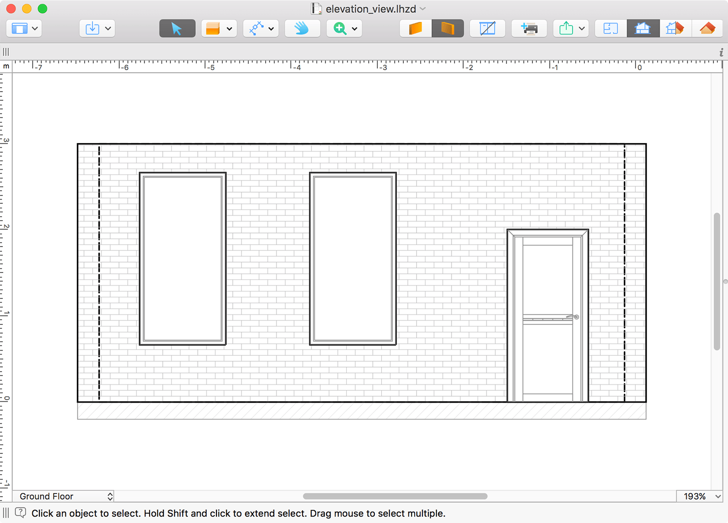
The 2D Elevation view displays the side view on walls and roofs. It is used to work with openings, niches and wall panels, and also to export and print elevations.
The functionality described in this section is only available in the Pro edition.
To open the 2D Elevation view, select a wall or roof segment, and click the 2D Elevation View button in the toolbar. You can do the same by selecting a niche, opening or wall panel, if this object is installed into a wall or roof.
The Toolbar
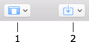
1 – The View button lets you control the Library and Inspector.
2 – Import 3D models from the Trimble 3D Warehouse™ online library or from files on your hard drive.

3 – The Selection tool for selecting and moving objects.
4 – Tools for drawing niches, openings and wall panels.
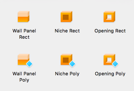
The Wall Panel Rect tool creates a rectangular wall panel.
The Wall Panel Poly tool lets you create a custom-shaped wall panel.
The Niche Rect tool creates a rectangular niche.
The Niche Poly tool lets you create a custom-shaped niche.
The Opening Rect tool creates a rectangular opening.
The Opening Poly tool lets you create a custom-shaped opening.
5 – Auxiliary tools.
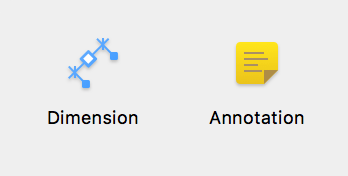
The Dimension tool lets you measure the distance between specified points.
The Annotation tool adds text boxes for typing or pasting text.
6 – The Pan tool lets you grab and scroll the 2D Elevation view with the mouse.
7 – The Zoom button lets you choose the Zoom In or Zoom Out tool.
8 and 9 – You can show one or the other wall side. You can also choose a roof side if you are editing a roof.
10 – Show or hide furniture. See Furniture in the Elevation View for more details.
11 – Print the current elevation. This button doesn't start printing immediately, but it adds the current elevation to the list in the Print Layout dialog. To print several elevations, you should add all of them to the print queue. You can then open the Print Layout dialog, choose views from the list, and actually print them.

12 – Export your floor plan, elevation or 3D view to one of the social networking sites, export it to your hard disk or attach it to a message.
13 – Display the 2D Plan view.
14 – Display the 2D Elevation view.
15 – Display the 2D and 3D views together (Split Mode).
16 – Display the 3D view.
Adding Objects from the Library
The 2D Elevation view allows you to add objects to the drawing which can be installed into walls and roofs. These are niches, openings, doors, windows and wall panels. To add an object, simply drag and drop it from the library into the project.
Creating Objects
You can draw niches, openings and wall panels directly in the 2D Elevation view using the drawing tools mentioned earlier. Each of the objects has two related tools. One can draw rectangular shapes, and another can create polygons.
To add a rectangular object, activate one of the Rect tools. Click and hold down the mouse button to start drawing a rectangle. You should then move the cursor to a new position and release the button.
To add a polygonal object, activate one of the Poly tools. Click several times in the 2D Elevation view to add corners. Double click in order to specify the position of the last corner of the polygon and deactivate the tool.
Changing the Shape of an Object
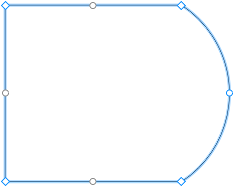
To modify the shape of niches, openings and wall panels directly in the 2D Elevation view, right-click on the object's contour and choose Edit Contour from the context menu. The resize handles will disappear indicating the contour editing mode. The program will display the object's outline with diamond-shaped handles at the corners called "points". To change the shape of the outline, you can move the points.
To add a new point, right-click on the contour and choose Add Point. To remove a point, right-click on it and select Remove Point.
In the contour editing mode, the program also displays round handles in the middle of each side of the outline. If you move a round handle in one or another direction, the corresponding side will bend inside or outside of the shape creating an arc. While you are changing the curvature of a side, a number near the cursor changes from 0 (straight line) to 180 (semicircle). One of possible ways to create a circle is to draw a square and bend each side up to 90 degrees. Hold down the Shift key to snap to 15 degree steps.
When the Edit Geometry option in the Inspector is unlocked, you can activate the editing mode by double-clicking on the object.
Furniture in the Elevation View
In order to show or hide furniture and Building Blocks in the elevation view, use the Furniture button in the toolbar.
A piece of furniture or Building Block will be displayed only if the gap between it and a selected wall is less than 1 meter or 39.4 in.
The 2D Elevation view lets you move furniture around and add new objects.